
Products
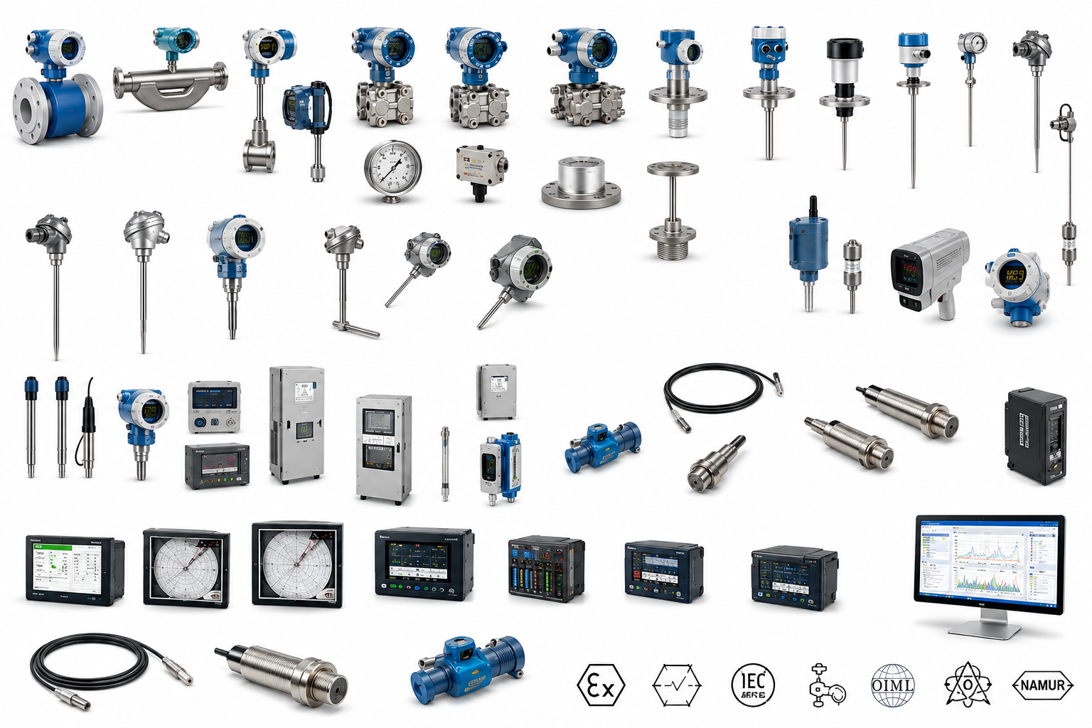
Instrumentation & Measurement
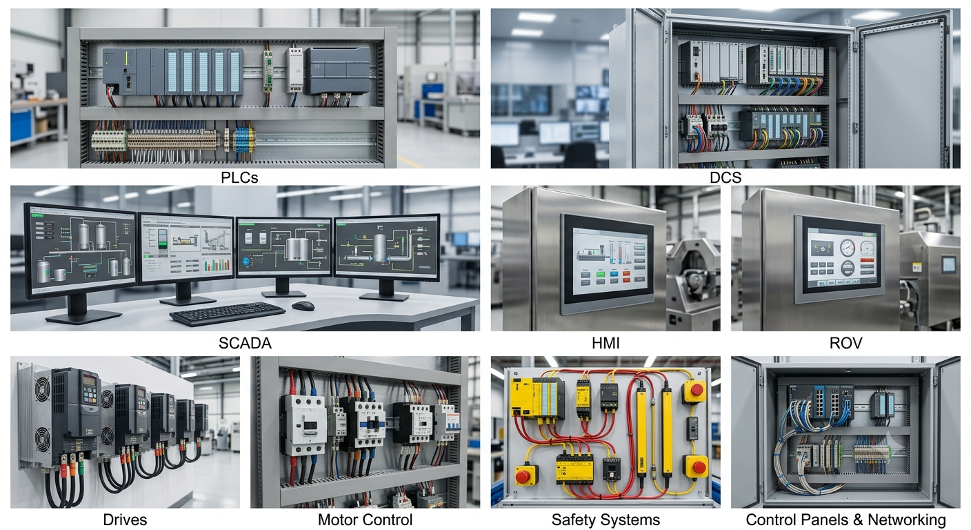
Control Systems & Automation
Valves & Flow Control
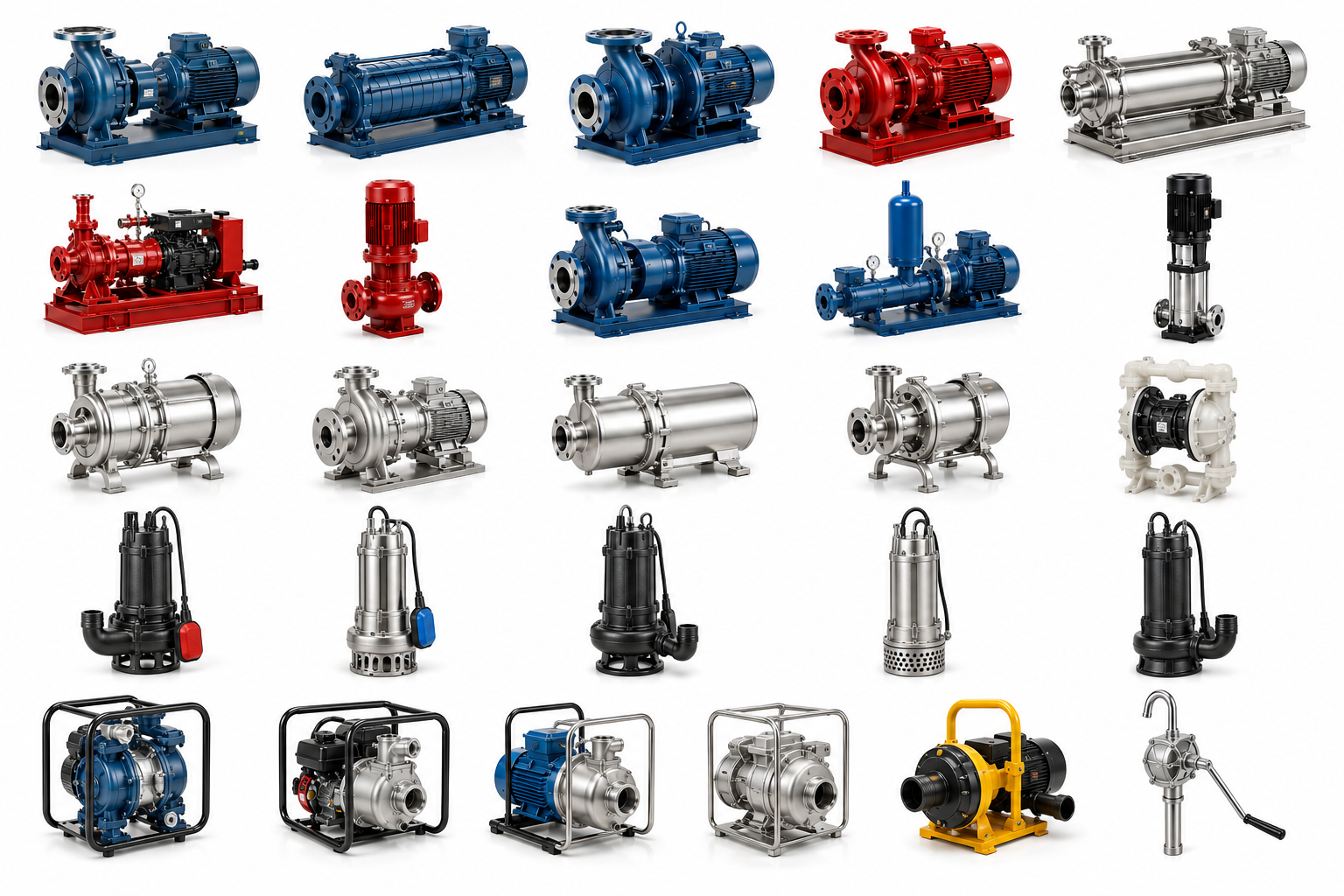
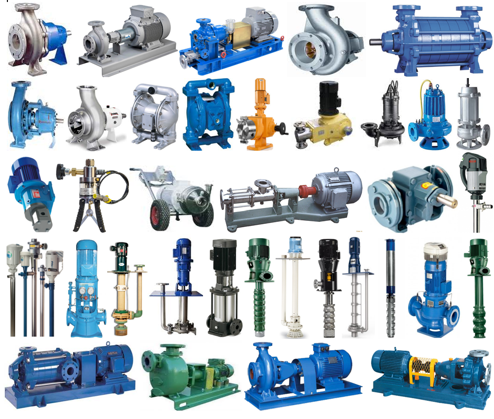
Pumps
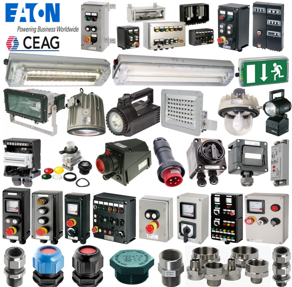
ATEX & Explosion-Proof Equipment
Fire Protection & Detection
Ignition & Flame Systems
Power Transmission
Tank Gauging & Storage Systems
Cables
Water Treatment & Desalination
Energy Storage & Backup Power
Cathodic Protection
Oil & Gas Drilling Parts
Industrial Spare Parts
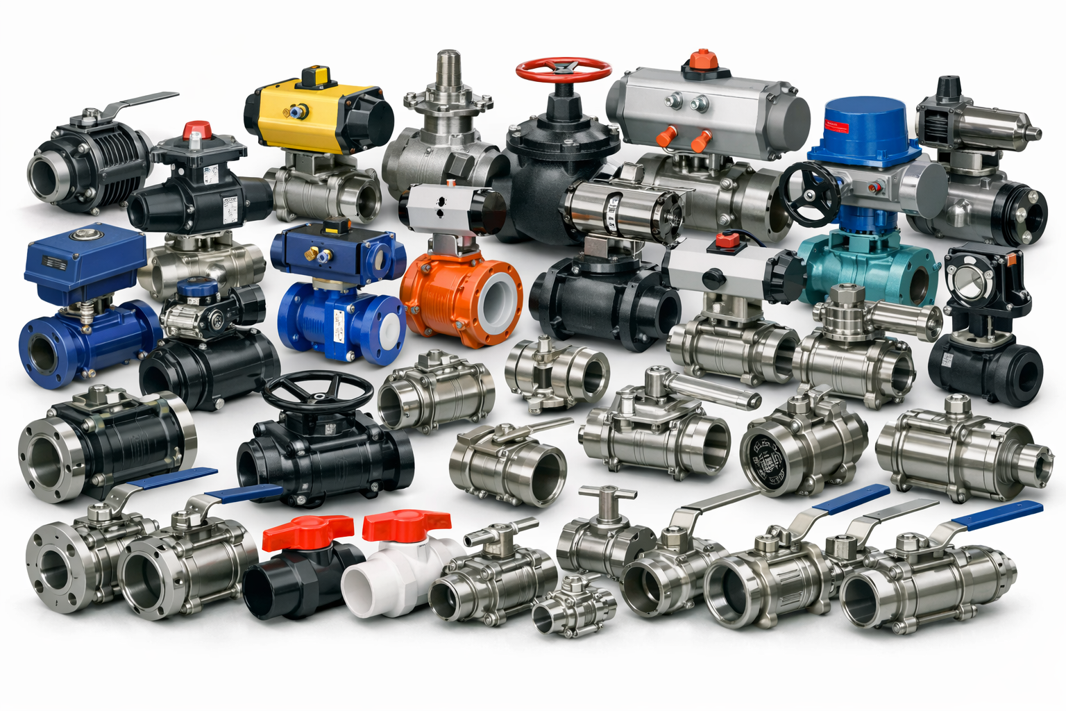
Ball Valves
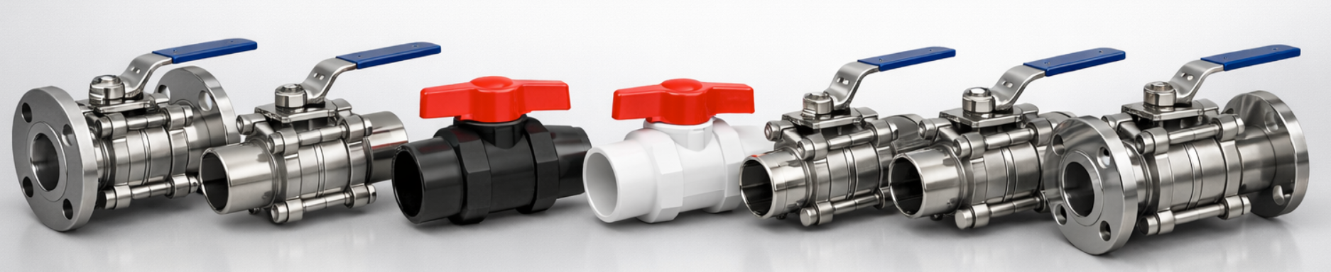
Gate Valves
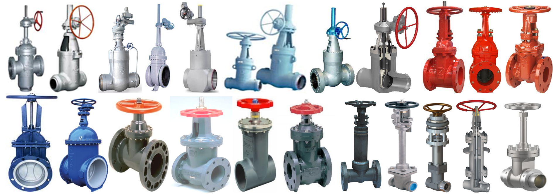
A gate valve is a valve that operates using a round/rectangular gate (wedge) out of the path of the fluid. The distinct feature of a gate valve is the sealing surfaces between the gate and seats are planar, so gate valves are often used when a straight-line flow of fluid and minimum restriction is desired. The gate faces can form a wedge shape or they can be parallel. Typical gate valves should never be used for regulating flow, unless they are specifically designed for that purpose.
On opening the gate valve, the flow path is enlarged in a highly nonlinear manner with respect to percent of opening. This means that the flow rate does not change evenly with stem travel. Also, a partially open gate disk tends to vibrate from the fluid flow. Most of the flow change occurs near shutoff with a relatively high fluid velocity causing disk and seat wear and eventual leakage if used to regulate flow.
Typical gate valves are designed to be fully opened or closed. When fully open, the typical gate valve has no obstruction in the flow path, resulting in very low friction loss.
Gate valves are ideally suited for petroleum applications because they perform well with viscous fluids.
Type of gate valves as follows:
• Parallel Slide Gate Valve
• Pressure Seal Gate Valve
• Wedge Gate Valve
• Expanding Gate Valve
• Geothermal Gate Valve
• API 6D Pipeline Gate Valve
• API 6A Wellhead Gates Valve
Stem of gate valves can be :
• Rising Stem
-Rising stems provide a visual indication of valve position because the stem is attached to the gate such that the gate and stem rise and lower together as the valve is operated.
• Non-Rising Stem
-Non-rising stem valves may have a pointer threaded onto the upper end of the stem to indicate valve position, since the gate travels up or down the stem on the threads without raising or lowering the stem.
-Non-rising stems are used underground or where vertical space is limited
Bonnets of gate valves can be :
-Bonnets provide leak proof closure for the valve body.
• Screw-in
-Simplest, offering a durable, pressure-tight seal
• Union
-Suitable for applications requiring frequent inspection and cleaning
-Also gives the body added strength
• Bolted Bonnet
-Used for larger valves and higher pressure applications
• Pressure Seal Bonnet
-This construction is adopted for valves for high pressure service
-A unqiue benefit of a pressure seal bonnet design is that the seal improves as the internal pressure in the valve increases
-Compared to other constructions where the increase in internal pressure tends to create leaks in the body-bonnet joint
Globe Valves
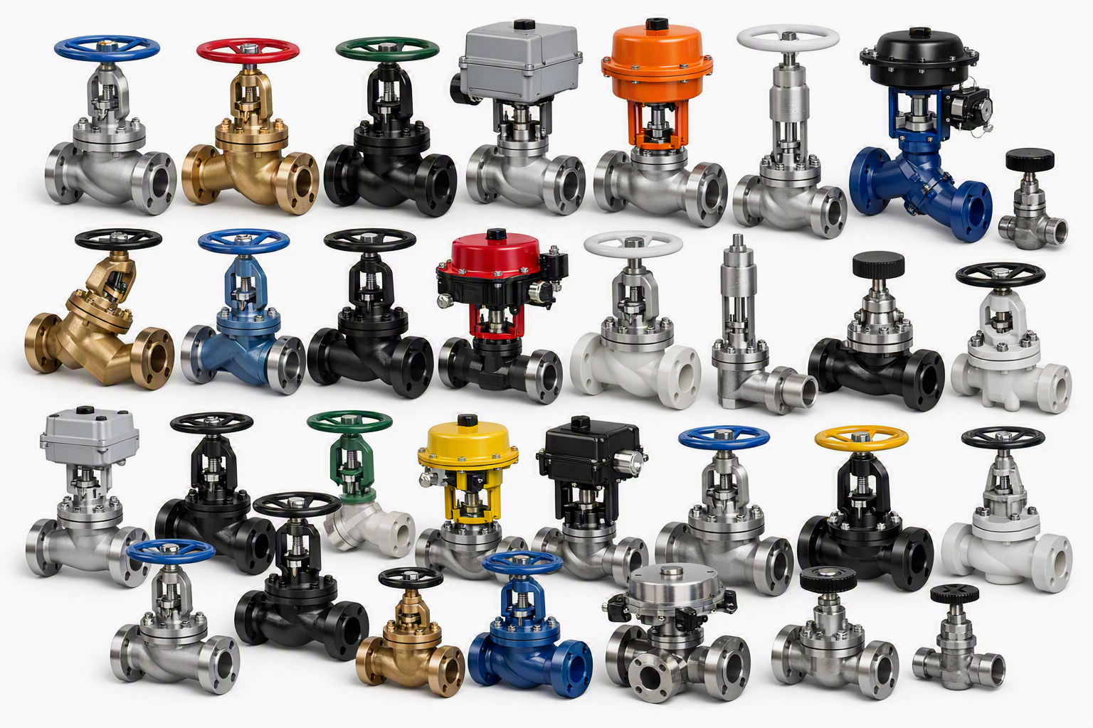
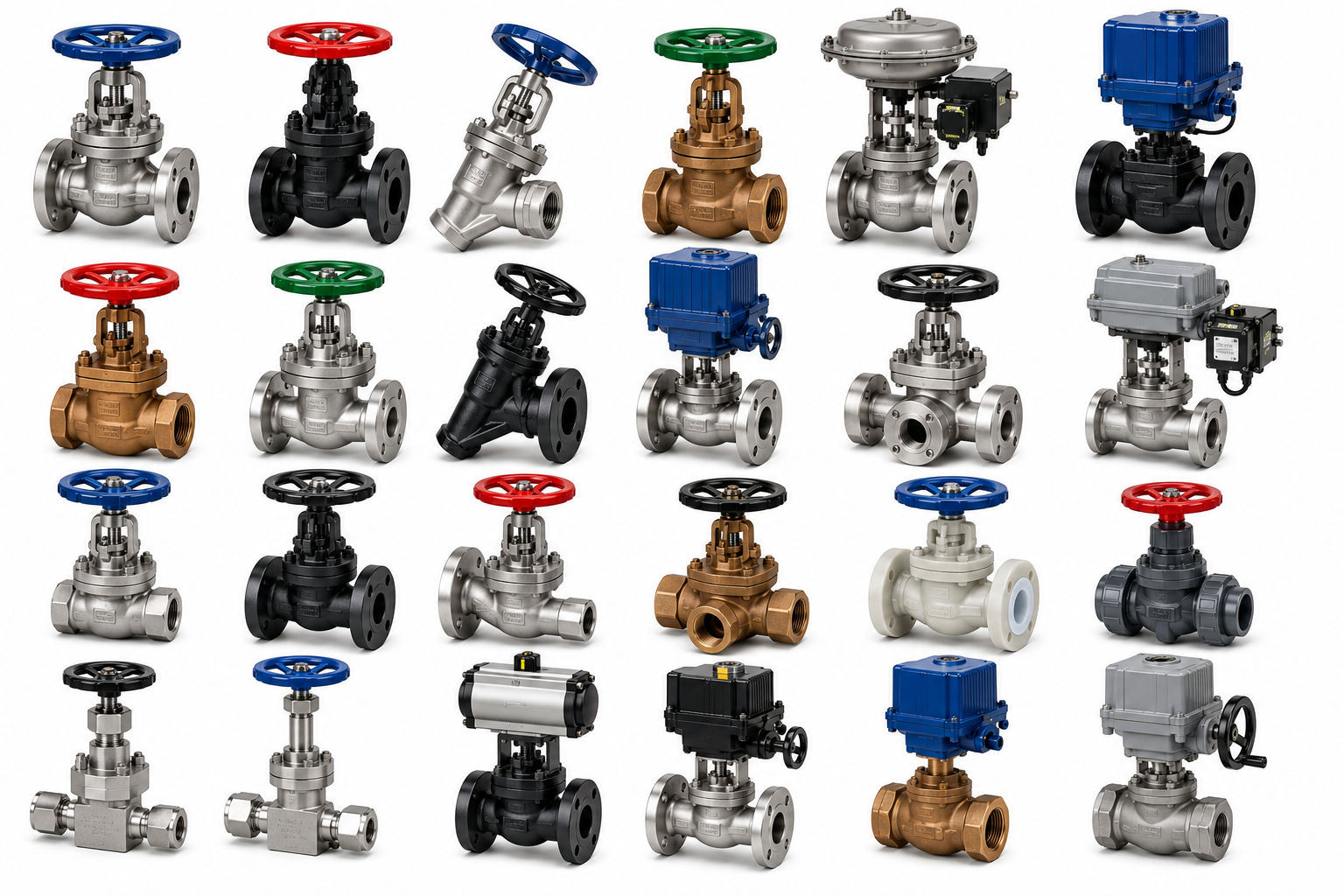
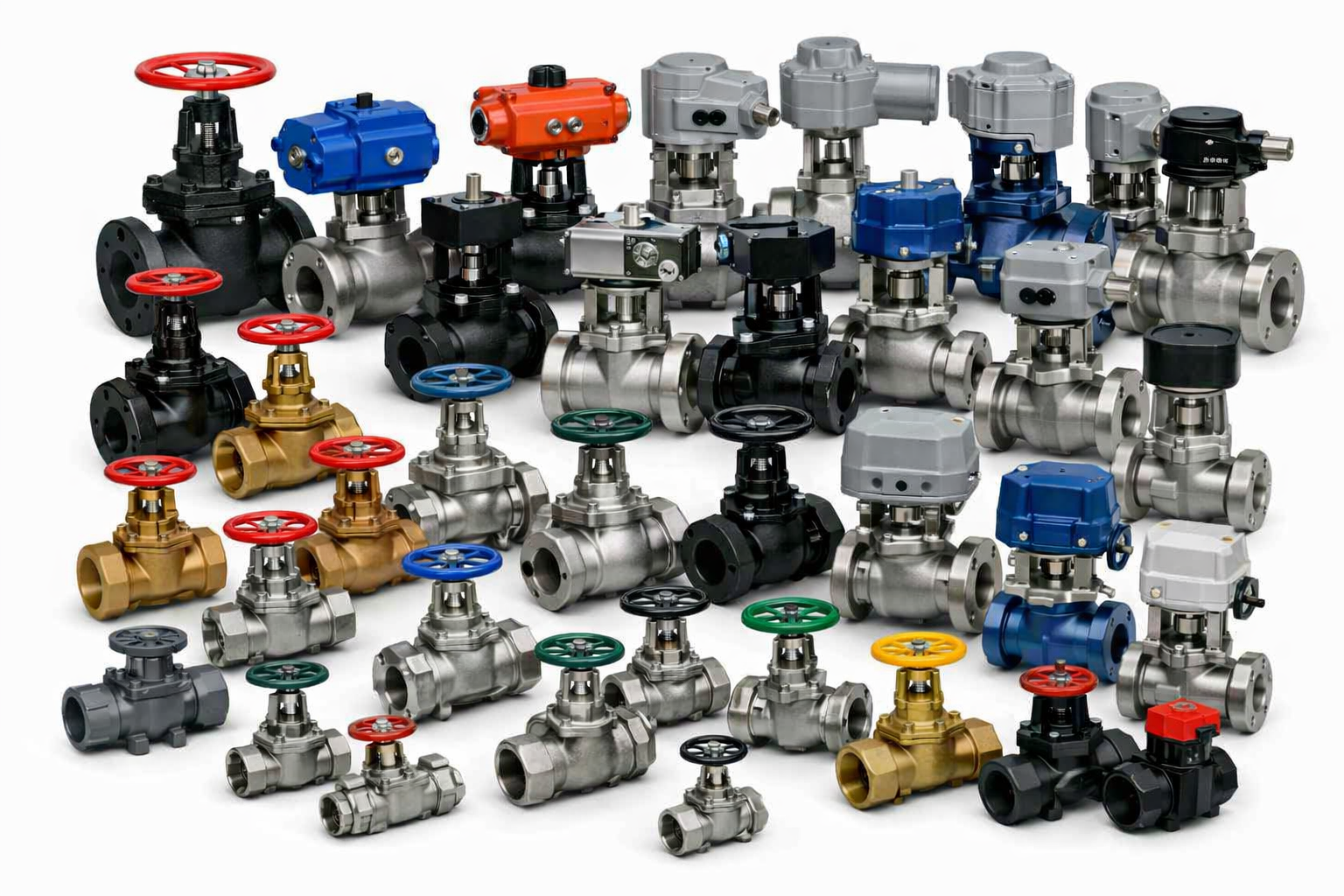
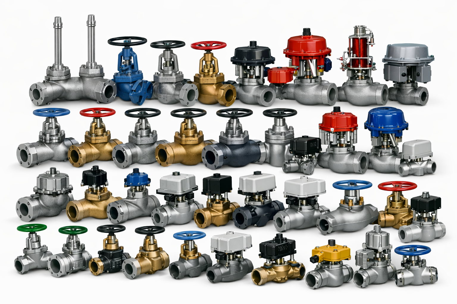
Globe valve is a linear valve used to start, stop and regulate flow. The globe valve disk can be completely or partially removed from the flow or it can completely close the flow.
Globe valves are used for applications requiring throttling and frequent operation. For example, globe valves or valves with a similar mechanism, may be used as sampling valves, which are normally shut except when liquid samples are being taken. Since the baffle restricts flow, globe valves are not recommended where full, unobstructed flow is required.
Used primarily for regulating flow in a pipeline, globe valves are the top choice for oil & gas, petrochemical and hydropower industries because of their smooth operation and tested reliability. Globe valves have a spherical body that is internally separated by a baffle. The opening in the baffle forms the seat in which the disk (plug) is lowered into to close or shut the valve to stop the flow of fluids. The proportional relationship between the disk and the seat enables precision flow regulation.
All globe valves provide leak-proof operation, resistance to harsh chemicals and environments, and extended life under frequent operation
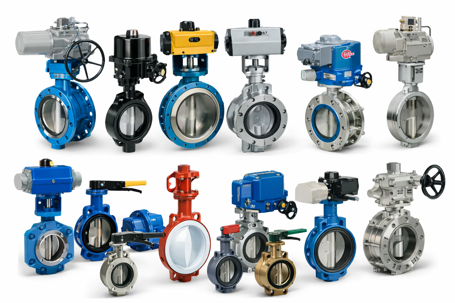
Butterfly Valves
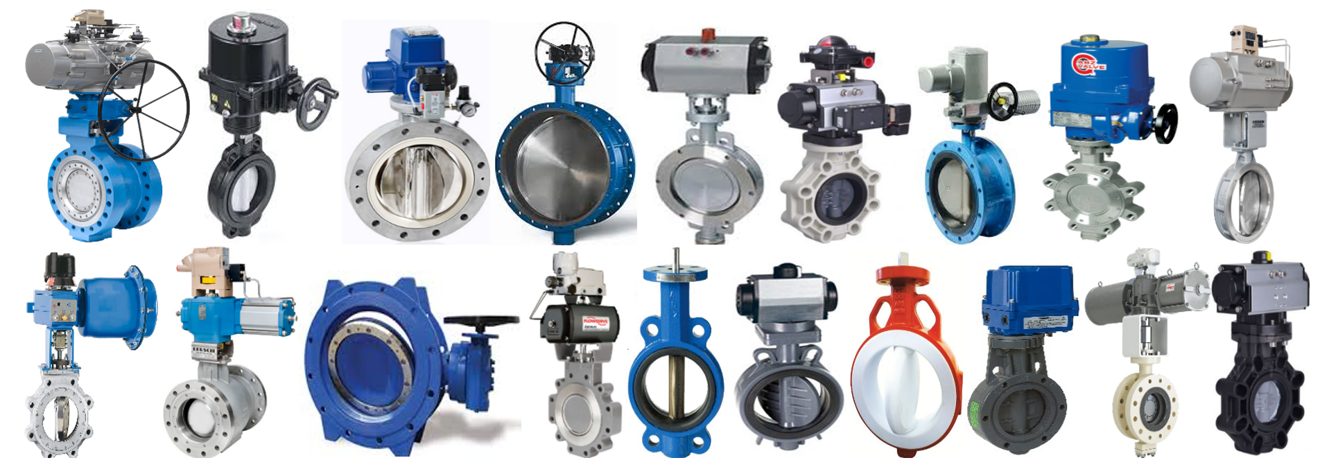
Butterfly valves are used for isolating or regulating flow. They are a quarter turn valve similar to a ball valve except the closing mechanism is a disk instead of a ball. Butterfly valves are typically lower in cost to other valve types as they are lighter in weight meaning less support is required to have them in line. The disc of the valve is operated by either a lever, gear or actuator. When the valve is closed the disc blocks the flow- when open the disk turns to allow flow to pass through; however the disk will always be present within the flow resulting in a pressure drop regardless of valve position. Butterfly valves can also be open incrementally to throttle flow.
Type
• Wafer Style or Lug Style – typical
◦ Designed to maintain a seal against bi-directional pressure differential to prevent backflow in systems designed for unidirectional flow
◦ Accomplishes this with a tightly fitting seal, i.e., gasket, o-ring, precision machined, and a flat valve face on the upstream and downstream sides of the valve
◦ A lug-style butterfly valve used in dead end service generally has a reduced pressure rating
◦ For example, a lug-style butterfly valve mounted between two flanges has a 150 psi pressure rating.
◦ The same valve mounted with one flange, in dead end service, has a 75 psi rating
• Flanged
– it is not uncommon to see a flanged butterfly valve in high performance applications
◦ Have threaded inserts at both sides of the valve body
◦ Allows Flange Butterfly Valve to be installed in a system using two sets of bolts and no nuts
◦ Installed between two flanges using a separate set of bolts for each flange
◦ This setup permits either side of the piping system to be disconnected without disturbing the other side
• Concentric Butterfly Valve
◦ Has a resilient rubber seat with a metal disc.
• Double Eccentric Butterfly Valve
◦ also known as a High Performance Butterfly Valves or Double Offset Butterfly Valve
◦ Different type of materials are used for the seat and disc.
• Triple Eccentric Butterfly Valve
– also known as Triple Offset Butterfly Valve
◦ Seats are either laminated or a solid metal seat design
◦ Design prevents gulling and scratches between the metal seat and the metal disc due to its unique construction
◦ Only time the seal comes into contact with the seat is at the point of complete closure
◦ Generally used in applications which require bi-directional tight shut-off in Oil & Gas, LNG/NPG terminal and tanks and Chemical Factories
◦ Widely used for dirty/ heavy oil to prevent extrusion.
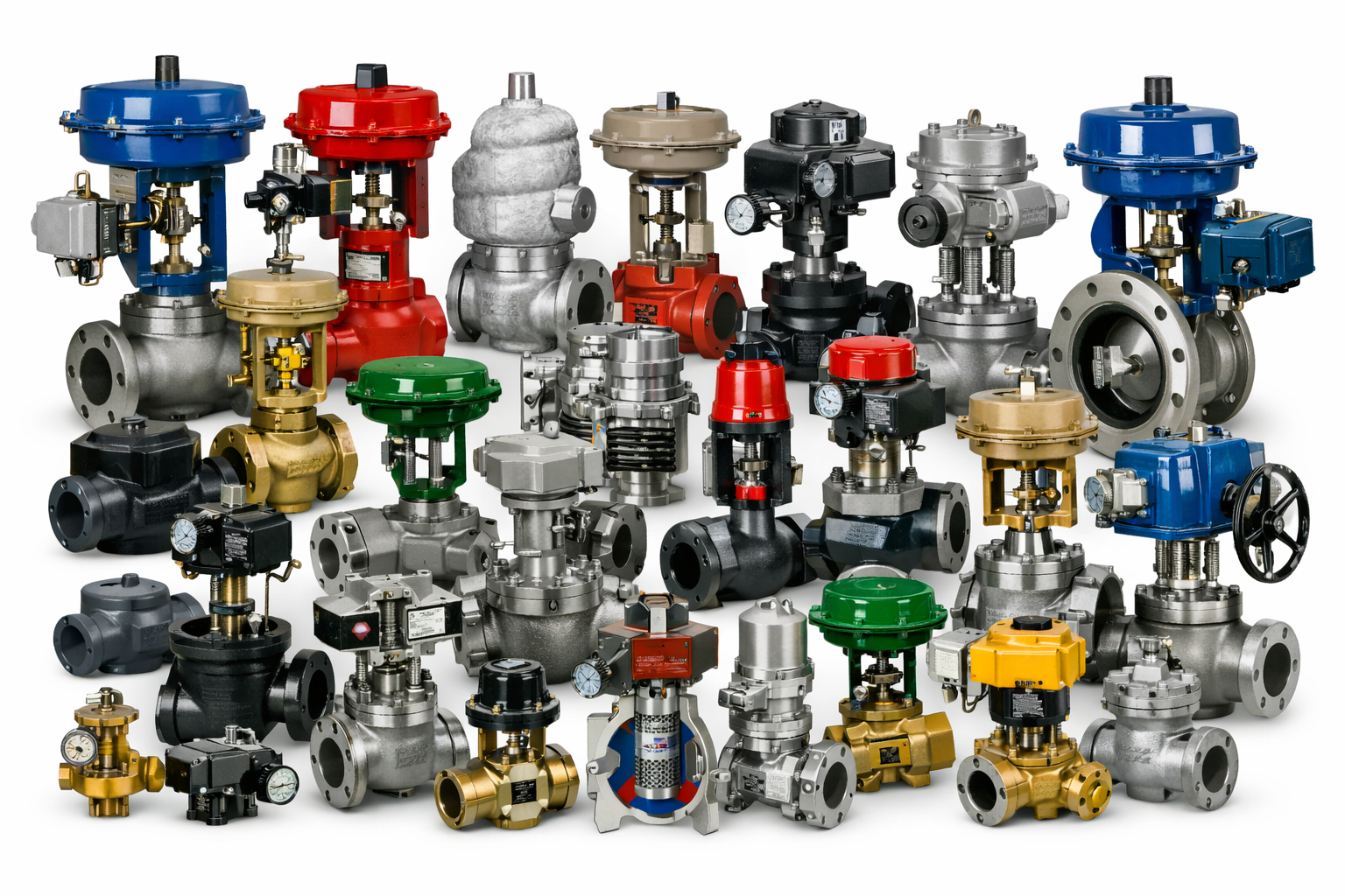
Control Valves
Control Valve working, Components & Types:
A control valve is used as a final control element in a closed loop system to automate specific processes which involves transportation of fluids from one place to another. It is a device which is used to control the flow rate of the fluid by varying the size of the flow passages. The size of the flow passages is dictated by a signal which can neither be pneumatic, hydraulic or electrical in nature. The flow rate of a flowing fluid is controlled directly using a control valve using which process quantities such as liquid level, temperature and pressure can be controlled indirectly. They can be seen as consequences of the control action on the flow rate of the fluid. The signal instructions are given by a controller present in the closed control loop.
Working of a Control Valve
The controller present in the closed loop feedback system of the process sends signal to the final control element, the control valve to instruct it how much to maintain the opening of the valve stem so as the flow rate can be increased, decreased or maintained at a steady state. If the signal is of pneumatic type then it corresponds to the range of 3-15 psig and if the signal is of electrical nature it corresponds to the range of 4-20 mA. A control valve operates is this range. In order to ensure that the valve stem position is changing as per the set point and the signal dictated by controller, a valve positioned is mounted near a valve assembly.
Components of a Control Valve
The main components of a control valve are the valve itself, the actuator and the valve positioner.
The valve:
This is the modulating element of the control valve within which a ball, plug, butterfly or plug is contained. The basic designs of the valve are of two types; a plug and seat design valve wherein a plug is pressed against a seat and a quarter turn valve wherein a ball, disc or cone is rotated and turned against a seat. The portion of the valve which regulates the flow is known as valve trim. Variety in designs of valve trims creates.
The actuator:
Its function is that it is used to move the valve stem. The moving action can be carried out either pneumatically, hydraulically or electrically. The air actuating valves are the simplest of the lot because they only require a supply of compressed air. The electrically actuated valves require additional cabling as well as a switch gear. The hydraulically actuated valves require high pressure supply lines and return lines as well for the hydraulic fluid.
Valve positioner:
A valve positioner’s function is to ensure that the position of the valve stem corresponds to the set point from the controller system. It requires the position feedback from the valve stem and it delivers pneumatic pressure to actuator to open or close the valve.
Types of Control Valves
The types can be various depending on the actuating medium used, functionality, movement profile of the controlling element.
Based on Actuating Medium used
Manual Valve:
They are not part of the automatic system of the process. They contain a hand wheel or a lever and are operated on by hand.
Pneumatic Valve:
They are actuated by a compressed material medium. The most common medium is Air. Other mediums like nitrogen, hydrocarbons, etc can also be used.
Hydraulic Valve:
They are actuated by a non-compressible material medium. The most common medium is usually water and sometime oil is also used.
Electric Valve:
They are actuated by an electric motor.
Based on Functionality of the valve
Proportional Control Valve:
The flow rate is controlled by an automatic proportional action based on the signal received by the controller. The valves which can be used are ball valve, globe valve, etc.
On-Off Valve:
The valve is either fully close or fully open. The valves which can be used are gate valve, ball valve, globe valve, etc
Check Valve:
Based on Movement profile of the Controlling Element
Sliding Stem:
It contains a plug and a seat setup. The valve stem and valve plug are one and the same thing. The plug slides in a linear motion. For example, globe valve, wedge valve. Etc.
Rotary Valve:
It contains a disc which under goes a rotary motion, the turning action results in a flow passage. For example, ball valve, butterfly valve, etc.
.png)